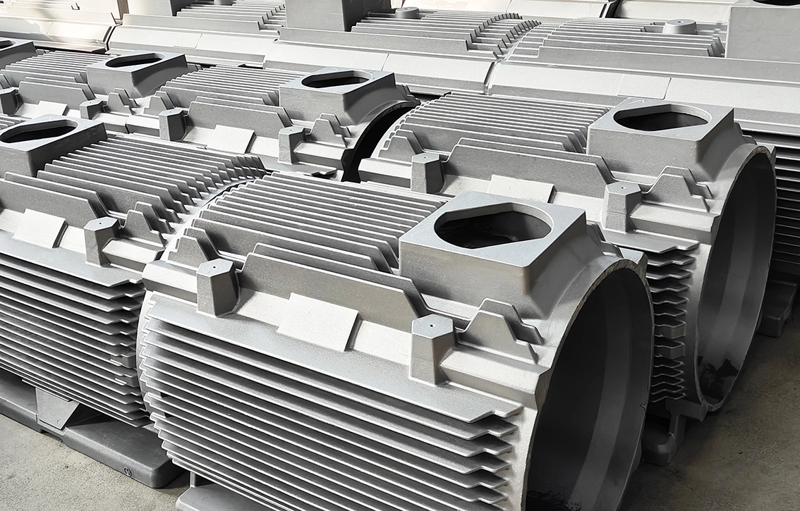
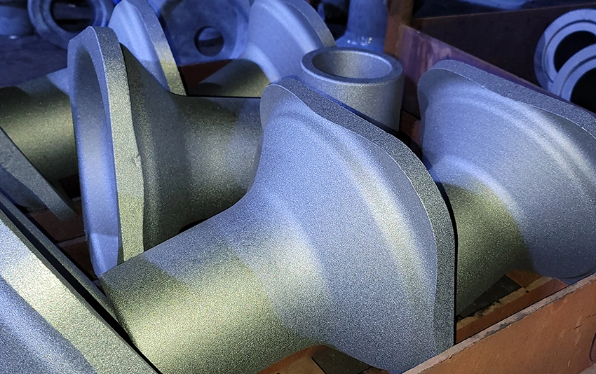
Applications of CNC Grinding for Castings and Forgings
1. Surface Grinding:
2. Cylindrical Grinding:
3. Centerless Grinding:
4. Profile Grinding:
5. Internal Grinding:
6. Deburring and Polishing:
7. Dimensional Corrections:
Machines Used for CNC Grinding
1. CNC Surface Grinders:
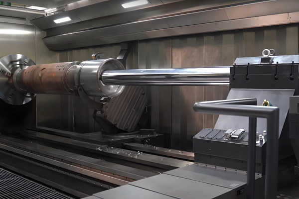
2. CNC Cylindrical Grinders:
3. Centerless Grinders:
4. CNC Tool and Cutter Grinders:
5. Double-Disc Grinders:
6. Precision Jig Grinders:
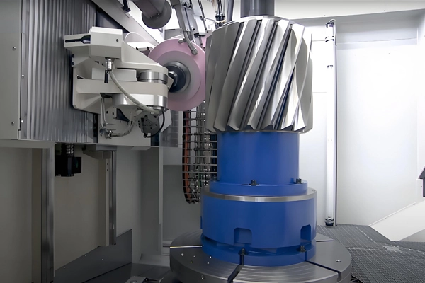
7. GLEASON AND KAPP NILES Gear Grinders:
Dimensional Inspection Measures
1. Coordinate Measuring Machines (CMM):
2. Surface Roughness Testers:
3. Roundness and Cylindricity Testers:
4. Optical and Laser Measurement Tools:
5. Micrometers and Dial Gauges:
6. Hardness Testers:
7. GLEASON Gear Measuring Machine:
Gleason Gear Measuring Machine is a precision instrument used for measuring and inspecting gears, particularly to assess their quality, accuracy, and dimensional conformance. It is commonly used in gear manufacturing industries where high-quality standards are required.
1. Profile Measurement: It measures the tooth profile of gears to ensure that the shape of the gear teeth matches the intended design. This includes the root, flank, and tip profiles.
2. Pitch Measurement: The machine measures the gear's pitch, which is the distance between corresponding points on adjacent teeth, ensuring that the gear teeth are evenly spaced.
3. Tooth Spacing and Runout: It checks for variations in tooth spacing and tooth runout, which can affect the gear's performance and smoothness of operation.
4. Gear Accuracy: The machine evaluates the overall accuracy of the gear, including deviations from the ideal or nominal shape and size. It can detect errors such as backlash, undercutting, or misalignment.
5. Pitch Diameter Measurement: The Gleason machine measures the pitch diameter of the gear, which is a key parameter for ensuring that the gear meshes properly with its mating gear.
6. Helix Angle Measurement: For helical gears, the machine can also measure the helix angle to ensure it conforms to the desired specifications.
7. Tooth Thickness Measurement: It ensures that the thickness of each tooth is within acceptable tolerances, which is crucial for the gear’s load-bearing capacity.
8. Load Capacity and Efficiency Testing: Some advanced Gleason machines also evaluate the operational load capacity and efficiency of the gear by simulating conditions similar to actual working environments.
9. Inspection for Surface Finish: The machine checks the surface roughness of the gear teeth, which is important for reducing friction, wear, and ensuring smoother operation.
10. Data Collection and Reporting: Modern Gleason machines are equipped with software that collects measurement data, analyzes the results, and generates reports to facilitate quality control and documentation.
Inspection Reports
1. Surface Finish Reports:
Documents roughness values, confirming smoothness and polish levels.
2. Roundness and Cylindricity Reports:
Certifies accuracy of cylindrical components.
3. Geometric Dimensioning and Tolerancing (GD&T) Reports:
Ensures features comply with design tolerances and positional requirements.
4. Material Inspection Reports:
Verifies no micro-cracks or alterations to the forged/cast material properties post-grinding.
5. Dimensional Inspection Reports:
Details critical measurements, deviations, and conformance to specifications.
6. Gear Manufacturing Reports:
1. Design and Specification Reports
· Gear Design Report: Includes the detailed specifications of the gear, such as the gear type (spur, helical, bevel, etc.), material specifications, dimensions, tooth profile, pressure angle, pitch, and other geometric features.
· Manufacturing Drawing: Detailed technical drawings that specify the exact dimensions and tolerances of the gear. This may also include annotations on heat treatment, surface finish, and other manufacturing instructions.
2. Material Certification Report
· Material Test Certificate (MTC): A report certifying the quality of the raw materials used in manufacturing the gears. This includes information about the material grade, composition, mechanical properties (tensile strength, hardness, etc.), and heat treatment specifications.
· Hardness Report: A specific test report showing the hardness level of the material used to ensure it meets the required specifications.
3. Manufacturing Process Reports
· Machining Process Report: Details the specific machining steps involved in producing the gears, including cutting methods (hobbing, shaping, grinding, etc.), tool selection, machine settings, and cutting parameters.
· Heat Treatment Report: A report detailing the heat treatment processes used for gears (e.g., carburizing, quenching, tempering) to achieve the required hardness, strength, and wear resistance.
· Surface Finish Report: Describes the surface finish of the gears, such as roughness (Ra), and ensures the gear surfaces meet the required standards to avoid excessive friction or wear.
4. Inspection and Measurement Reports
· Gear Geometry Measurement Report: A detailed report of the measurements taken from the gear, including tooth profile, tooth thickness, pitch, and diameter. This report ensures the gear conforms to the design specifications.
· Tooth Profile and Pitch Measurement Report: Specific measurements related to the tooth geometry, including root, flank, and tip profiles, as well as the gear’s pitch.
· Pitch Diameter and Runout Report: Provides measurements of the gear's pitch diameter and checks for any runout or wobble that could cause misalignment during operation.
· Tooth Spacing Report: This report checks the uniformity of tooth spacing around the gear, ensuring no defects like spacing errors or gaps.
· Backlash Measurement Report: A report that measures the gear’s backlash, which is the clearance between teeth in meshing gears, ensuring it falls within the acceptable range.
· Helix Angle and Lead Measurement Report: For helical gears, this report verifies the helix angle and lead, ensuring proper alignment and meshing of gears.
5. Quality Control Reports
· Dimensional Inspection Report: A full dimensional report detailing the measurements of the gear against its CAD design. This report will list any deviations from the intended dimensions and whether they are within acceptable tolerances.
· Visual Inspection Report: A report that highlights the results of a visual inspection, noting any surface defects, cracks, chips, or other visible imperfections.
· Defect Report: This report records any defects found during the inspection phase, categorizing them according to their severity (e.g., cosmetic, functional) and determining the need for rework or rejection.
6. Test Reports
· Load and Stress Test Report: If applicable, gears may undergo load testing to simulate their operational conditions. This report details the results of the tests, including stress levels and any performance issues such as deformation or failure.
· Fatigue and Durability Test Report: For gears used in critical or high-load applications, a test report may be created to simulate long-term usage and measure the gear's resistance to fatigue or wear.
7. Final Quality Assurance (QA) Report
· Final Inspection Report: A comprehensive report that consolidates all inspections, measurements, and tests performed on the gear, confirming that it meets all specified requirements and quality standards.
· Certification of Compliance: A report or document certifying that the gear conforms to all relevant standards, such as ISO, AGMA, or other industry-specific standards.
8. Packaging and Shipping Report
· Packaging Report: Details how the gears are packaged and protected for shipment, including the materials used and the method of packaging to prevent damage during transportation.
· Shipping Documentation: Includes the shipping details, such as the destination, order number, shipping date, and quantity shipped, along with any relevant customs or export documentation if applicable.
9. Traceability and Audit Reports
· Batch Traceability Report: This report tracks the manufacturing batch, material lots, and manufacturing processes used for each specific gear or gear set, ensuring traceability for quality assurance and recall purposes.
· Audit Report: A report detailing the internal or external audits conducted on the manufacturing process, quality control measures, and compliance with industry standards.
10. Non-Conformance and Corrective Action Report (CAR)
· Non-Conformance Report (NCR): If any part of the gear does not meet the specifications or tolerances, a non-conformance report is generated, outlining the nature of the issue.
· Corrective Action Report (CAR): In cases of non-conformance, a CAR is created to describe the corrective actions taken, which might include rework, redesign, or adjustments to the manufacturing process.
Quality Control Measures
1. Pre-Grinding Inspection:
2. Tool and Wheel Maintenance:
3. In-Process Monitoring:
Continuous tracking of grinding parameters, including speed, feed rate, and temperature, to avoid over-grinding or burns.
4. Post-Grinding Inspection:
5. Non-Destructive Testing (NDT):
6. Adherence to Standards:
7. Traceability:
Advantages of CNC Grinding for Castings and Forgings
1. Superior Surface Quality:
2. Tight Tolerances:
3. Versatility:
4. Enhanced Efficiency:
5. Extended Tool and Component Life:
 English
  Deutsch
  français
  русский
  فارسی
فارسی  العربية
  Español
  日本語
日本語  한국어
한국어  italiano
  português
  dansk
dansk  Suomi
Suomi 